


In our three-part series on residential roof framing basics, we’re examining critical components of residential roofs and the common misunderstandings related to these components, which often result in costly property damage, liability claims, and litigation.
We’ve discussed Ridge Boards vs Ridge Beams and Rafter Ties vs. Collar Ties; now in our third post, we discuss the function and proper construction of hips and valleys.
Using hips and valleys to create multi-faceted roofs is extremely common in residential construction as it makes for more dynamic and interesting rooflines. Unfortunately, along with the appealing aesthetics comes increased complexity of rooflines and increased potential for construction and design defects.
Code references throughout our discussion come from the 2015 edition of the International Residential Code (“IRC”), the most common edition currently adopted across the United States. Similar requirements and principles exist across other IRC editions and industry standards as well.
Hips And Valleys: Function, Configuration and Code Requirements
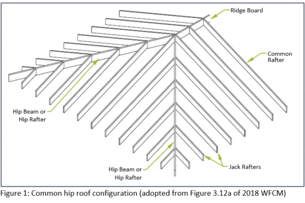
In the previous posts, we introduced the most common “conventional system” of roof framing wherein the roof is constructed with rafters along each slope with ceiling joists along the bottom enclosing an attic space and resembling a triangular shape when viewed from the side. Instead of a uniform triangular shape across the entire length of the roof, the corners of a conventional system can be framed into a convex (outward) shape at the corners to form a “hip.” The ridge can even be eliminated all together with the corners coming together to form a single peak in the case of a pyramid hip roof. A hip beam or hip rafter provides the main structural support for a hip shape and is defined by the Wood Frame Construction Manual (“WFCM”) produced by the American Wood Council (“AWC”) as follows:
“HIP BEAM – A beam spanning from the ridge to the OUTSIDE ROOF CORNER that supports the jack rafters, forming a CONVEX roof line.” [2018 WFCM]
The hip beam can be thought of as a secondary ridge that spans from the outside corner to the main peak of the roof. It primarily functions as a nailing board between opposing jack rafters. A common hip roof configuration is shown in Figure 1 below (adopted from the 2018 WFCM to illustrate the various components).
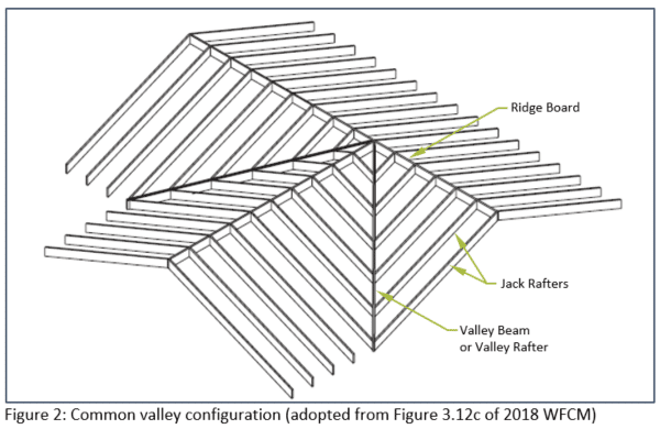
To form an opposite, concave (inward) shape in the roof system, a “valley” can be used and is often located at the intersection of different roof sections, e.g., when two gable roof sections intersect or in an “L”-shaped building configuration. A valley beam or valley rafter provides the main structural support for the valley shape and is defined by the WFCM as follows:
“VALLEY BEAM – A beam spanning from the ridge to an INSIDE ROOF CORNER, that supports the jack rafters, forming a CONCAVE roof line.” [2018 WFCM]
In the situation of a valley, all the jack rafters are inherently oriented downward toward the valley, creating loading behavior like a center floor girder that takes loading from joists. A common valley configuration is shown in Figure 2 (adopted from the 2018 WFCM to illustrate the various components).
In order to form a convex hip or concave valley, the rafters framing into the hip or valley beams on both sides need to be cut to varying lengths to accommodate the diagonal slope of the hip or valley beams. These rafters are referred to as jack rafters and are defined as follows:
“JACK RAFTER – A rafter that spans from a hip or valley beam to a wall plate or ridge, respectively.” [2018 WFCM]
Now that we have established the definition and basic function of hips and valley beams, let’s move on to the specific requirements of the building code regarding hip and valley beams along with illustrative examples on why those requirements exist. The IRC requirements for hip and valley beams are relatively brief and listed as follows in Section R802.3:
“At valleys and hips there shall be a valley or hip rafter not less than 2-inch (51 mm) nominal THICKNESS and not less in DEPTH than the cut end of the rafter. Hip and valley rafters shall be supported at the ridge by a BRACE to a bearing partition or be designed to carry and distribute the specific load at that point. Where the roof pitch is less than THREE UNITS IN 12 units horizontal (25-percent slope), structural members that support rafters and ceilings joists, such as ridge beams, HIPS AND VALLEYS, shall be designed as BEAMS.”
As can be seen, the IRC requirements for hips and valleys are lumped together and generally follow much of the same requirements of ridge boards and ridge beams. However, based on our review of the member loadings, there are fundamental differences between hips and valleys that should be considered and that dictate different design and construction practices. As such, we have separated the discussion of each into two separate sections.
Hips: Often Function Much Like a Non-Structural Ridge Board
The behavior and code requirements of a hip beam are analogous to a non-structural ridge board. Namely, the hip beam typically functions as a nailing board between opposing jack rafters. As long as the slope is above 3:12 and there are ceiling joists or rafter ties to resist the thrust at the bottom of the rafters, the opposing jack rafters on either side of the hip beam create a truss action that holds the hip beam upwards. At lower slopes, this behavior tends to break down and the hip needs to be designed and constructed as a structural beam. The minimum thickness and depth requirements ensure that the hip beam can function as a proper nailing board and provide sufficient bearing on opposing sides of hip beam. All these requirements are similar to the distinction between ridge board and ridge beam as discussed in the earlier post on those components.
For hip beams, IRC language also requires support (brace or wall) at the top of the hip beam. Although not explicitly stated in the IRC language, it is our experience that a brace may not be necessary with a steeper slope and there is sufficient framing and detailing to resist outward thrust. Figure 3 provides an illustrative example of insufficient bearing of a hip connection along with a missing vertical brace on a lower sloped roof, resulting in deflection of a hip roof as well as cracks on the interior during an historic snow fall event in western New York in November 2014.
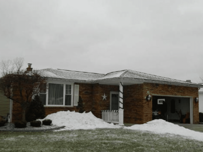
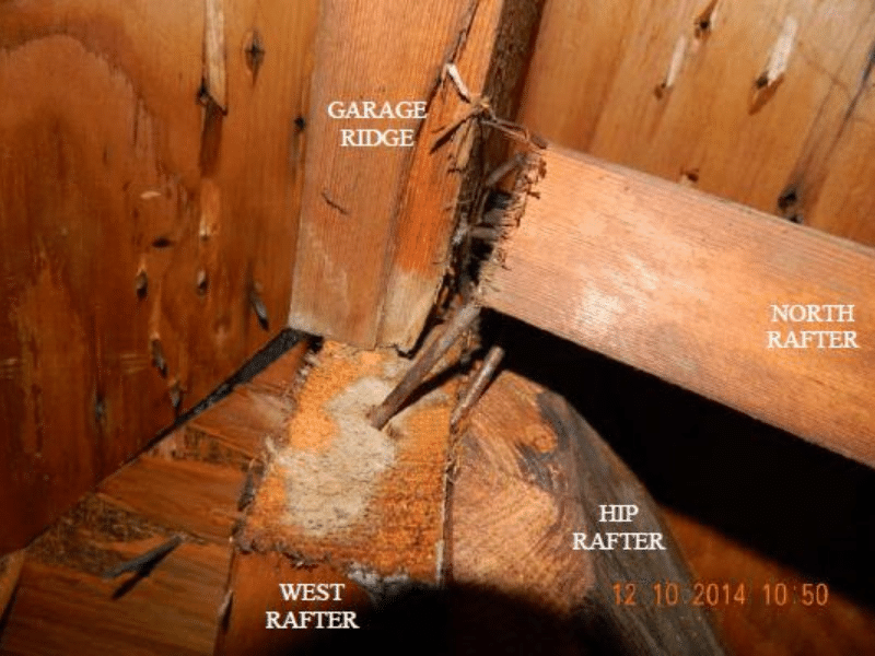
Figure 3: Example of insufficient bearing and lack of brace below hip causing deflection during an historic snow fall event
Valleys: Should Always Be Constructed as Structural Beams
As previously stated, in the situation of a valley, all the jack rafters are inherently oriented downward towards the valley, creating loading behavior like a center floor girder that takes loading from joists. Going strictly by the IRC language requirements, only a slope lower than 3:12 would require design and construction of the valley beam as a structural beam. However, based on experience and review of member loadings, the valley beam will necessarily behave as a structural beam, no matter the roof slope. For this reason, valleys should always be constructed as structural beams.
Similar to ridge beams, there are no specific tables in the IRC that provide the required sizing and connections for specific spans and loading like those for floor girders. As a result, contractors or architects may rely on lumber suppliers or just their own experience to size the valley beams. Complicating matters a bit more is the fact that valley beams typically support a more complex, overlapping triangular area of roof loading as compared to simpler rectangular areas. It should be noted that the WFCM does provide sizing guidance on valley beams for various loading and span conditions in Table 3.28 which can be utilized by contractors and architects when a structural engineer is not involved with the project. The other bearing geometry and brace requirements noted for hips are also applicable to valley beams with similar ramifications, including deflection and connection withdrawal if not properly followed.
When the valley beam is undersized and/or missing a brace, the valley can crack from overstress and cause downward deflection of the roof system as illustrated in Figure 4. This is a common mechanism of failure from snow loading either from an extreme one-time event like a blizzard or over time from cyclical seasonal loading. Because valley beams are often located at the intersection of multiple, overlapping roof slopes repairing a valley beam can be costly and involve shoring, repairs, and manipulation of a much larger area of framing then just the valley beam itself.
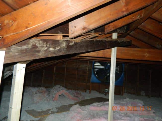
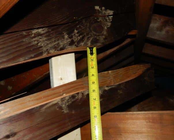
Figure 4: Example of undersized valley and missing brace causing valley beam to crack in half during historic snow fall in New England during winter of 2014-2015 (Note: light colored braces were only added afterwards as temporary shoring)
In our experience, a single member matching the same depth as the common rafters with no vertical brace is often incorrectly used when constructing a valley beam. Not only does the lack of brace and depth of the valley beam violate the IRC requirements, but there are also concerns regarding the structural capacity of the single member itself. As an example, if we consider a roof system that has a 10-foot horizontal span between the exterior walls and the main ridge with a dead load of 10 pounds per square foot (“psf”) and ground snow load of 30 psf, Table R802.5.1(3) of the IRC and Table 3.26D of WFCM would dictate a minimum rafter size of 2×6 for typical 16-inch spacing using Spruce Pine Fir No. 2. If the same roof system had a valley configuration with an associated 10-foot by 10-foot tributary area of loading, Table 3.28 of the 2018 WFCM would dictate a minimum valley beam size of (2)-2×10 (i.e. double 2×10). In this example, if a single 2×6 was used at the valley instead of a (2)-2×10, the valley beam would be grossly undersized by factor of almost five, based on the allowable moment capacity of each member. This exceeds the typical safety factors for wood framing which are between 2 and 3 depending on the mode of failure and can result in failure (cracks and deflection) of the undersized valley beam during significant one-time snow events or from cyclical seasonal loading.
The same example can also be used to illustrate how the IRC can be misleading on the topic of valley beam behavior. If the slope was above 3:12, the IRC language indicates the valley does not need to be constructed as a structural beam so a single 2×8 (matching the cut end of the jack rafters) may be incorrectly used by the contractor instead of a more substantial (2)-2×10 structural beam. Again, based on experience and review of member loadings, the valley beam will necessarily behave as a structural beam, no matter the roof slope.
Avoiding Complications Related to Hips and Valleys in Residential Roof Framing
Misunderstandings regarding the function, structural behavior, and code requirements for hips and valleys are common causes of property damage, liability claims and litigation in residential roof framing. A hip beam or hip rafter typically functions as a nailing board between opposing rafters in a convex (outward) roof slope change, similar to a ridge board. A valley beam or valley rafter provides the main structural support for a concave (inward) roof slope change. The code specifies minimum thickness and depth for hips and valleys beams and requires a brace to support the top end of the hip or valley beam. Although the code is misleading on valley beam behavior, it is our experience that valley beams will always behave as structural member regardless of slope due to the inherent downward loading from the jack rafters and should be designed and constructed as such. Hip beams, on the other hand, typically only need to be designed and constructed as structural members at slopes less than 3:12.
For in-depth insights into hips and valleys, as well as other residential roof framing best practices, don’t hesitate to reach out. We’re here to assist you in achieving the highest standards in residential construction and design.
Authored by, Eric Ryan, PE, SE, LEED AP, Sr. Structural Engineer, Assistant Vice President.