Thermal remediation is an effective but often costly technology for the expedited remediation of high concentrations of a wide range of environmental contaminants in a variety of settings. Thermal remediation technologies rely on the addition of energy (heat) to the subsurface to change the phase distribution and other physical properties of contaminants, inducing mobilization and aiding in recovery.
With in-situ thermal remediation (ISTR), vapors are recovered by soil or multi-phase vacuum extraction, brought to the surface, and then treated before discharge. Contaminants that can be treated include:
- volatile organic compounds (VOCs)
- semi-volatile organic compounds (SVOCs)
- polychlorinated biphenyls (PCBs)
- pesticides
- creosote/coal tar
- per- and polyfuoroalkyl substances (PFAS)
Thermal remediation can be applied to a wide range of subsurface lithologies including clay, sand, gravel and fractured bedrock and in hydrogeologic settings both above and below the groundwater table. Another advantage of thermal remediation is that it can be used near critical infrastructure, below buildings or streams, and in and around sensitive utilities.
Thermal Remediation Technologies
Thermal remediation technologies are very aggressive and are most applicable for sites (or portions of sites) where contaminant concentrations are the highest (i.e., “source areas”), including areas where light or dense nonaqueous phase liquid (“LNAPL” or “DNAPL”) is present. Thermal remediation technologies have the advantage of being relatively fast, with remediation of most VOC contamination requiring one year or less of system operation to recover large percentages of the contaminant mass. Using temperature measurements to ensure treatment of the target area greatly increases the certainty of the remediation effectiveness.
The most common in-situ thermal remediation technologies are:
- thermal conductive heating (TCH), sometimes called in-situ thermal desorption (ISTD)
- electrical resistance heating (ERH)
- steam enhanced extraction (SEE)
An additional, emerging thermal technology referred to as self-sustaining technology for active remediation (STAR), results in the in-situ combustion of liquid contaminants that have significant fuel value in porous media. Each of these technologies are discussed below.
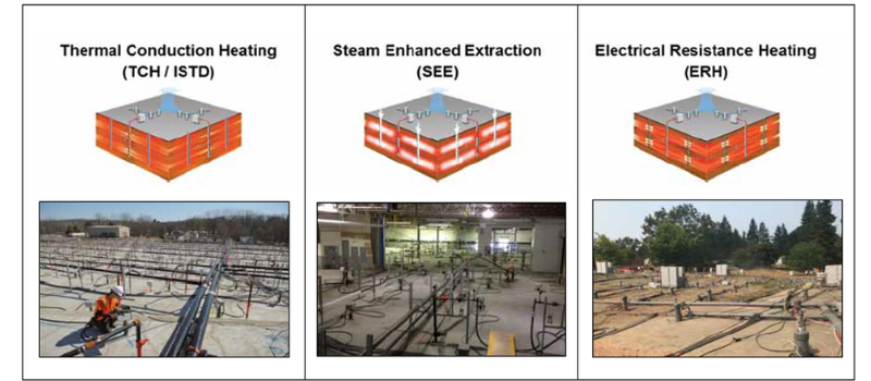
Examples of Wellfields for the Three Primary Thermal Remedial Technologies

Image Source: TerraTherm, Inc.
Thermal Conductive Heating (TCH)/In-Situ Thermal Desorption (ISTD)
TCH/ISTD relies on heat conduction through the soil to the target treatment area and was first developed by Shell Oil Company in the 1990s. Thermal conductivity of different soil types is fairly uniform but is low, requiring a steep temperature gradient (thus high temperatures) at the points of energy application in order to transport energy away from the points of application. Heater wells with temperatures in the range of 500o to 800oC are typically used, with heater well spacings of 6 to 20 feet, depending on the time available for remediation.
Most TCH systems rely on electrical energy, however, one version uses natural gas or propane combustion at the well heads. The heater wells are installed in a triangular pattern at spacings of 12- to 20-feet, with extraction wells located throughout the treatment area, generally at the midpoints between the heater wells. When installed above the water table, treatment temperatures up to 400oC can be reached to treat higher boiling compounds. TCH is the only method that can reach temperatures above the boiling point of water and in the higher temperature applications (temperatures of 350o – 400oC), the heater spacing is typically 8 to 12 feet.
Multiple well patterns are used to increase heating effectiveness/efficiency and vapor extraction is used to recover the vaporized contaminants. Because it does not rely on water for energy application or convection, temperatures above the boiling point of water can be achieved when the soils are unsaturated, which allows not only VOCs but also SVOCs to be effectively treated.
Angled or horizontal wells can also be used and are installed in triangular patterns, creating a series of hexagons. Energy applied to the heater wells creates temperatures of 500o – 800oC at the wells, but due to the steep temperature gradient, only soils within approximately 6 to 12 inches of the heater wells reaches temperatures above the boiling point of water. Vacuum extraction can be:
- built into the heater wells;
- adjacent to (within 3- feet of) the heater wells; or,
- at centroid locations between the heater wells
Treatment durations range from several months to about a year, depending on the temperature required for volatilization of the contaminants and the selected well spacing. When treating below the water table, higher permeability soils will result in longer treatment times or necessitate a tighter well spacing, as water flow through the treatment area will cause heat to migrate from the treatment area. TCH technology is applicable for groundwater flow rates less than 0.1 to 1 foot per day. Where higher flow rates are encountered, barriers such as sheet piles or slurry walls have been used to reduce the effects of groundwater flow.
For the recovery of SVOCs, PCBs and coal tar contaminants, the target temperature may be as high as 350oC, depending on the boiling point of the contaminant and the degree of treatment desired. These high treatment temperatures can only be achieved above the water table, or when the water table is controlled to eliminate ground water flow into the treatment area.
Recently, effective treatment of PFAS soil contamination using TCH has been demonstrated. PFAS concentrations in soil were reduced from an average of 232 μg/kg to 4.1 μg/kg and PFAS compounds were observed to breakdown over a wide temperature range.
Superfund sites where TCH has been used effectively include:
- Solvent Recovery Services of New England in Connecticut
- Memphis Depot Superfund site
- Velsicol Superfund site in Michigan (chlorinated solvents)
- Mare Island Naval Shipyard site in California (PCBs)
Electrical Resistance Heating (ERH)
ERH was first developed by Pacific Northwest National Laboratory in the early 1990s. With ERH, electrodes are typically installed vertically in a hexagonal pattern, spaced 12- to 20-feet apart and a 3-phase alternating current is applied, as it allows for a better current distribution in irregularly shaped treatment areas.
ERH relies on water in the pore spaces to carry current between the electrodes. Soils are naturally resistant to the current flow and this resistance dissipates the current energy as heat. Volatile contaminants are vaporized and extracted via soil vapor extraction (SVE). Temperatures equivalent to the boiling point of water can be achieved with this technology, but water must be maintained in the pores for current to continue to flow. Thus, in low permeability soils or when treating soils above the groundwater table, water or an electrolyte solution is usually added to ensure that contact is maintained between the electrodes and thus heating is maintained.
Some versions of the ERH also rely on water injection to carry energy convectively from the electrodes and thus greater water injection rates are used. In this case, groundwater extraction is always used in conjunction with vapor phase extraction. A variety of electrode constructions have been used, including steel pipe or copper plate, with a backfill of conductive materials such as graphite or steel shot in the borehole annulus to increase the effective diameter of the electrode (typically 10 to 12-inches). The electrodes are typically installed vertically in a hexagonal pattern, 12- to 20-feet apart.
Groundwater flow rates greater than one foot per day are challenging for ERH systems and may limit the system’s ability to reach the boiling point of water and/or lead to a loss of hydraulic control. In these situations, groundwater extraction upgradient of the treatment area with reinjection downgradient may flatten the hydraulic gradient and extend the use of this technology to more permeable saturated formations. Another option is to limit groundwater flow into the treatment area by installing an upgradient hydraulic barrier such as a sheet pile wall or slurry wall.
Superfund sites where ERH has been used successfully include:
- East Gate Disposal Yard at the Fort Lewis Army Depot in Washington (waste oil and chlorinated solvents)
- Cleburn Street Well in Kansas (chlorinated solvents)
- South Municipal Well Superfund site in New Hampshire (chlorinated solvents)
- Hamilton-Labree Superfund site in Washington (chlorinated solvents)
Steam Enhanced Extraction (SEE)
SEE involves the injection of steam under pressure with the concurrent extraction of groundwater, NAPL and vapors. Each multiphase extraction well is ideally surrounded by four to six injection wells. Pore fluids (water and NAPL) will be displaced by the steam and condensate, pushing it toward the extraction wells. Volatile compounds with a boiling point of less than approximately 150oC will be essentially fully recovered by the passage of the steam front.
SEE is most effective in more permeable soils with hydraulic conductivity greater than 10-3 centimeters per second (cm/sec). The groundwater extraction rate must exceed the steam injection rate by a factor of 1.5 to 2.5 to maintain hydraulic control by also recovering the groundwater displaced by the growth of the steam zone.
Ex-Situ Applications/Treatment Piles
Thermal remediation (most commonly TCH or ERH) can also be used in ex-situ applications, within an engineered, above ground, fully enclosed treatment pile structure. Ex-situ applications have been used for contaminated shallow soils that cannot be practically treated in-situ and may be more appropriate for high-boiling compounds such as PCBs, dioxins and furans or PFAS that are more easily excavated without causing excessive fugitive emissions of volatile contaminants, but for which offsite disposal is not an option or is very costly.
The principles of the system are the same as for in-situ treatment, in that heater wells or electrodes or are installed to heat the soil and vaporized contaminants are extracted under vacuum. Treatment piles typically range in size from 50 to 70,000 cubic yards.
Self-Sustaining Technology for Active Remediation (STAR)
Self-sustaining technology for active remediation (STAR) is an emerging smoldering combustion technology applicable to SVOCs such as coal-tar based products or heavy petroleum hydrocarbons that have more limited volatility but significant fuel value.
At the ignition point, a heater is inserted to start the combustion process. The combustion process itself produces the energy required to continue to volatize the contaminants as the combustion front migrates away from the ignition point. Air must be injected to sustain the process and this process works above and below the water table. Volatile compounds are collected via vacuum extraction along with the products of combustion, which are treated through vapor phase granular activated carbon (GAC) before discharge.
The smoldering combustion process destroys the higher boiling point NAPL components in-situ, producing carbon dioxide, carbon monoxide and water vapor. Lighter components of the NAPL, such benzene, toluene, ethylbenzene and xylenes (BTEX) are generally volatilized before the combustion front reaches them. The combustion products as well as the volatile components of the NAPL (typically less than two percent of coal tar) are extracted via vacuum extraction.
This technology typically requires NAPL concentrations in excess of 3,000 to 5,000 mg/kg.
Effects of Increasing Temperature
All forms of thermal remediation involve increasing temperature, which causes exponential increase in vapor pressure, exponential decrease in viscosity of water and NAPL, increased solubility of contaminants and decreased adsorption, all of which aid in the remediation process.
Temperature increase also affects organic chemicals, inducing greater mobility, increasing vapor generation, increasing flow to extraction wells and inducing degradation reactions (oxidation, pyrolysis, hydrolysis), all of which also aid in the remediation process.
Selecting Applicable Technology for a Site
While ERH and TCH are more applicable in lower permeability soils and SEE requires more permeable soils, there is overlap in the applicability of these technologies depending on the
- contaminant to be remediated;
- geologic and hydrogeologic setting;
- remedial action goals
For SVOCs, the permeability of the soils, the hydrogeologic setting and the remedial goals will all be important in selecting the most appropriate technology. For sites where the contamination resides in both high permeability and low permeability soils, a combination of thermal technologies can be used in conjunction with one another and may be the optimal approach.
Selecting a remediation technology requires the evaluation of a variety of factors, including contaminant type, geology, permeability, hydraulic conductivity, thermal conductivity and electrical resistivity, all of which are interrelated. It is Important to use and seek design input from well-qualified and experienced vendors.
Summary
Thermal remediation is an approach involving technologies with a proven track record that rely on the addition of energy to the subsurface to increase temperature and change the phase distribution and other physical properties of volatile and semi-volatile organic contaminants to mobilize them and aid in their recovery.
Thermal remediation is an aggressive approach, best suited for source zones/areas of high contaminant concentrations, including areas of non-aqueous phase liquids/free product. The approach has the advantage of being relatively fast, with remediation of volatile organic compounds commonly achievable within one year at many sites.
Several different thermal remediation technologies (or combinations thereof) are available to remediate a wide range of contaminants under a wide range of geologic lithologies and hydrogeologic settings. Thermal remediation is generally one of the most effective remediation approaches available but may also be the most expensive option due to the associated energy costs. Unit costs for thermal radiation typically range from about $100 to $500 per cubic yard treated.
Lastly, all sites are different and it is important to have well qualified, experienced personnel involved in the selection of the optimal technology and remedial system design, which typically requires a thorough and often complex analysis involving full site characterization and a good understanding of site conditions.
The Vertex Companies, LLC (VERTEX), with an extensive staff of professional engineers, professional geologists, environmental scientists and remediation specialists, can provide assistance with the evaluation of the potential applicability of thermal remediation at sites and selection of an optimal approach and system design based on site specific conditions. VERTEX can also assist insurance carriers with the evaluation of claims involving the use of thermal remediation made on pollution insurance policies. For more information, please contact Lawrence Daniels (ldaniels@vertexeng,com) or call +1.781.952.6000 or submit an inquiry.


