Series: Residential Roof Framing Basics
Part 1: Ridge Board vs. Ridge Beam
Part 2: Rafter Tie vs. Collar Tie
Pat 3: Hips and Valleys (Coming Soon)
Errors in the design and construction of residential roof framing are common causes of property damage, liability claims and litigation. In our experience performing hundreds of forensic evaluations related to residential roof framing per year, the problems often stem from misunderstanding of the following three critical components of residential roofs:
This three-part series aims to provide an overview of these critical components in an effort of providing an overview of residential roof framing basics, code requirements, and common deficiencies. Part 1 on ridge boards and ridge beams can be read here. In Part 2, we will discuss the difference between rafter ties and collar ties (and no – they are not the same thing!). Code references throughout our discussion come from the 2015 edition of the International Residential Code (“IRC”), the most common edition currently adopted across the United States. Similar requirements and principles exist across other IRC editions and industry standards as well.
The most common type of residential roof is a simple gable or hip configuration, consisting of a peak (ridge) and sloped sides, resembling a triangular shape when viewed from the side. When vertically loaded, the ridge tends to deflect downward, and the bottom of the rafters tends to push outward, i.e. the triangular shape flattens down and out. A rafter tie is a horizontal framing member that extends across the roof span to resist the outward thrust at the bottom of the rafters and effectively “tie” the rafters into their proper triangular shape. Its function and location is summarized in the following definition from Wood Frame Construction Manual (“WFCM”) produced by the American Wood Council (“AWC”):
“RAFTER TIE – A structural framing member located in the LOWER THIRD of the attic space that ties rafters together to RESIST THRUST from gravity loads on the roof.” [2018 WFCM]
In a “conventionally” framed roof, a roof is constructed with rafters along each slope with ceiling joists along the bottom enclosing an attic space. In this configuration, the ceiling joists also function as rafter ties (Fig. 1).
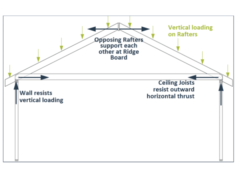
Figure 1: Diagram of conventional system with ceiling joists acting as rafter ties.
In addition to providing support to any vertical attic ceiling loads, the ceiling joists must also be designed and constructed to withstand the tension along their length, caused by the outward thrust at the exterior walls. To ensure proper performance as a member in tension, i.e. rafter tie, Section R802.3.1 of the IRC specifies the following for ceiling joists in a conventional system:
“Ceiling joists and rafters shall be nailed to each other in accordance with Table R802.5.1(9), and the rafter shall be nailed to the top wall plate in accordance with Table R602.3(1). Ceiling joists shall be continuous or securely joined in accordance with Table R802.5.1(9) where they meet over interior partitions and are nailed to adjacent rafters to provide continuous tie across the building where such joists are parallel to rafters.”
When ceiling joists are not connected to the rafters at the top of the wall, e.g. in an open or cathedral system, Section R802.3.1 of the IRC goes on to stipulate that additional framing must be installed in order for the joists to function as a rafter tie:
“Where ceiling joists are not connected to the rafters at the top wall plate, joists connected higher in the attic shall be installed as rafter ties, or rafter ties shall be installed to provide a continuous tie. Where ceiling joists are not parallel to rafters, rafter ties shall be installed. Rafter ties shall not be less than 2 inches by 4 inches (nominal), installed in accordance with the connection requirements in Table R802.5.1(9), or connections of equivalent capacities shall be provided.”
The requirements in both of the previous code excerpts aim to ensure that rafter ties:
When rafter ties are not present – often the case when ceiling joists are installed perpendicular to rafters – the exterior walls tend to bow outwards as the ridge deflects downward under vertical loading. In our experience, this is the most common cause of failures observed during loading from a one-time snowstorm or repeated seasonal snow loading events. Deflection of the exterior walls from missing rafter ties can be extensive, costly to repair and even lead to collapse if the rafters completely detach from the exterior walls. Fig. 2 illustrates an example of exterior walls that bowed outward several inches following a record season of New England snowfall in 2014-2015, along with corresponding displacement and cracks to finishes on the interior and framing in the attic. In this case, the ceiling joists were installed perpendicular to the rafters and no rafter ties were present.
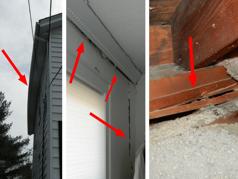
Figure 2: Example of outward bow of exterior walls as well as displacement and cracks to finishes on the interior and framing in attic.
Beyond ensuring that rafter ties are present, the IRC requires that rafter ties be positioned in the lower third of the attic space. This placement represents the most efficient design for the performance of the tie and prevents excess deflection or overstress of the rafters. Rafter ties can technically function at heights above the lower third but doing so requires rafter and connection design by a licensed engineer because the configuration is outside the scope of the prescriptive IRC. Moving the rafter tie up increases bending stress and deflection concerns on the rafters which must be accounted for in the size and connection detailing of the rafter, as reflected in the IRC rafter span tables (Tables R802.5.1(1)-(8)) with the factor Hc/Hr. When Hc/Hr is less than 1/7.5, no adjustments to rafter spans are needed. When Hc/Hr is 1/3 (maximum allowed), the applicable adjustment in rafter span is 0.67. This means the allowable span length listed in the table would need to be reduced by 33% because the rafter tie has been moved upward. Positioning the rafter ties too high without adequate rafter or connection consideration often results in cracks and displacement in the rafters (Fig. 3).
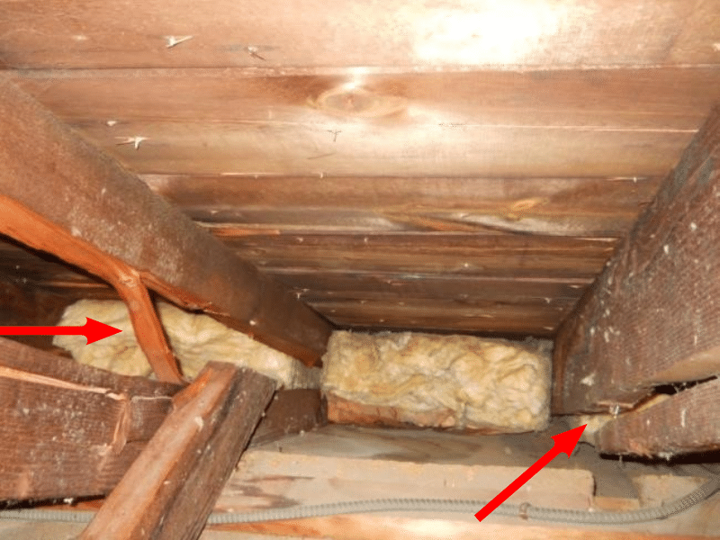
Figure 3: Example of failed rafters because rafter ties installed too high
Finally, to function properly as a continuous horizontal tie across the roof span, the ends of the rafter ties must be properly connected to the bottom of the rafters (heel joint) and any splices along the length of the rafter ties must be properly connected to each other. Maintaining a continuous tie with an adequate number of fasteners at these connections is crucial to the overall performance of the roof framing system. Inadequate fasteners or flawed connection geometry are common mistakes that can result in cracks and displacement from long-term framing deflection or seasonal snow loading. Design and construction professionals who are not familiar with residential framing are often surprised at the number of fasteners required at these connections. For reference, a typical roof span of 28 feet with a 5:12 pitch and 16-inch rafter spacing would require seven (7) 16d common nails (0.148”x3.5”) for a ground snow load of 30 pounds per square foot (“psf”) in accordance with Table R802.5.1(9). In general, as the slope of the rafters decreases, i.e., the triangle flattens, the thrust force increases and, consequently, the number of fasteners required increases. Fig. 4 provides an example of failed connection due to inadequate number of fasteners.
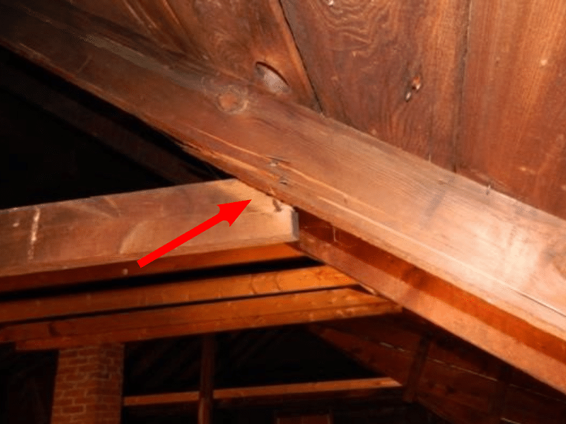
Figure 4: Example of connection failure due to inadequate number of fasteners (Note rafter ties also installed too high in attic space)
When properly understood, rafter ties can be designed and constructed in a variety of ways and remain effective, even if outside the scope of the prescriptive IRC requirements. In a recent restaurant renovation where Vertex was engineer of record, steel tension rods created the desired open ceiling layout and provided the inherent tension behavior required of rafter ties (Fig. 5).
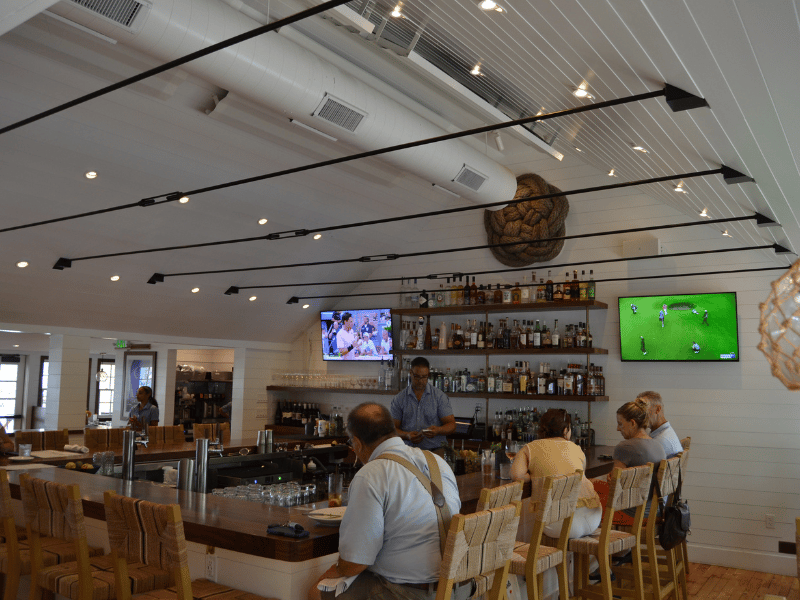
Figure 5: Example of unique rafter tie design from recent project: Sail Loft Restaurant Renovation
As discussed in Part 1, it should be noted that open ceiling configurations do not necessarily need rafter ties provided there is a properly designed and constructed ridge beam.
Collar ties, installed near the top of the attic space, serve a very different purpose than a rafter tie. The WFCM provides another useful definition regarding the location and purpose of collar ties:
“COLLAR TIE – A structural framing member located in the UPPER THIRD of the attic space that ties rafters together to RESIST ROOF SUCTION loads at the ridge.” [2018 WFCM]
Wind blowing across a structure produces upwards suction or uplift on the roof of the structure. In typical gable or hip configurations, the wind uplift generated tends to pull the tops of the rafters apart at the ridge. Collar ties or ridge straps are the most common method to resist this outward suction force at the ridge and keep the rafters connected at the peak. The collar ties essentially keep the roof from “un-zipping” along the ridge during a high wind event.
To ensure proper performance as a collar tie in a conventional system, Section R802.3.1 of the IRC specifies the following:
“Collar ties or ridge straps to resist wind uplift shall be connected in the upper third of the attic space in accordance with Table R602.3(1). Collar ties shall not be less than 1 inch by 4 inches, spaced not more than 4 feet on center.”
In our experience, roof failures from inadequate or missing collar ties occur primarily during high wind events such as hurricanes and tornadoes. Therefore, proper construction of collar ties is particularly critical in coastal high wind zones and areas prone to tornadoes. These uplift failures can be extensive and can lead to progressive collapse of the residence during high wind events (Fig. 6)
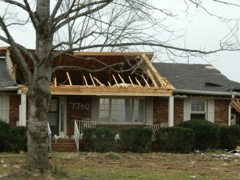
Figure 6: Example of uplift failure along ridge during high wind event
Now that we have introduced the function and location of both rafter ties and collar ties, it’s useful to discuss a common occurrence: the dreaded mid-height tie. Installing framing at mid-height of the attic space typically does not serve either purpose (protecting against the results of gravity or high winds) adequately without additional design considerations. This is commonly observed in open ceiling layouts or partially sloped/vaulted ceilings. During our investigations, it’s common to discover that a design professional and/or contractor thought it would be more useful to install ties at the mid-height of the attic space with the thought that it will function better in its role as a rafter tie or perhaps serve dual purpose as both rafter tie and collar tie.
Rafter ties and collar ties serve very different purposes in residential roof framing. Confusion about their function and proper location commonly results in errors in the design and construction of roof framing which can often lead to property damage, liability claims, and litigation.
The IRC provides prescriptive requirements for the location, sizing and connections of both rafter ties and collar ties. When desired framing layouts or as-built conditions exist that are outside of that defined in the prescriptive IRC, a licensed design professional is typically required to provide adequate framing sizing and connection design.
In our next post (Part 3), we will discuss hips and valley as we continue our overview of residential roof framing basics.
To learn more about VERTEX’s Forensic Consulting Services and Expert Witness Services, or to speak with a Forensic Engineering Expert, call 888.298.5162 or submit an inquiry.
Authored by: ERIC RYAN PE, SE, LEED AP
SR. STRUCTURAL ENGINEER AND ASSISTANT VICE PRESIDENT, FORENSICS
Part 1: Ridge Board vs. Ridge Beam
Part 2: Rafter Tie vs. Collar Tie
Pat 3: Hips and Valleys (Coming Soon)